Noritsu 120AFC II Roller and Belt Replacement Instructions

Written by Leah Weir, Owner of Poji Film Lab

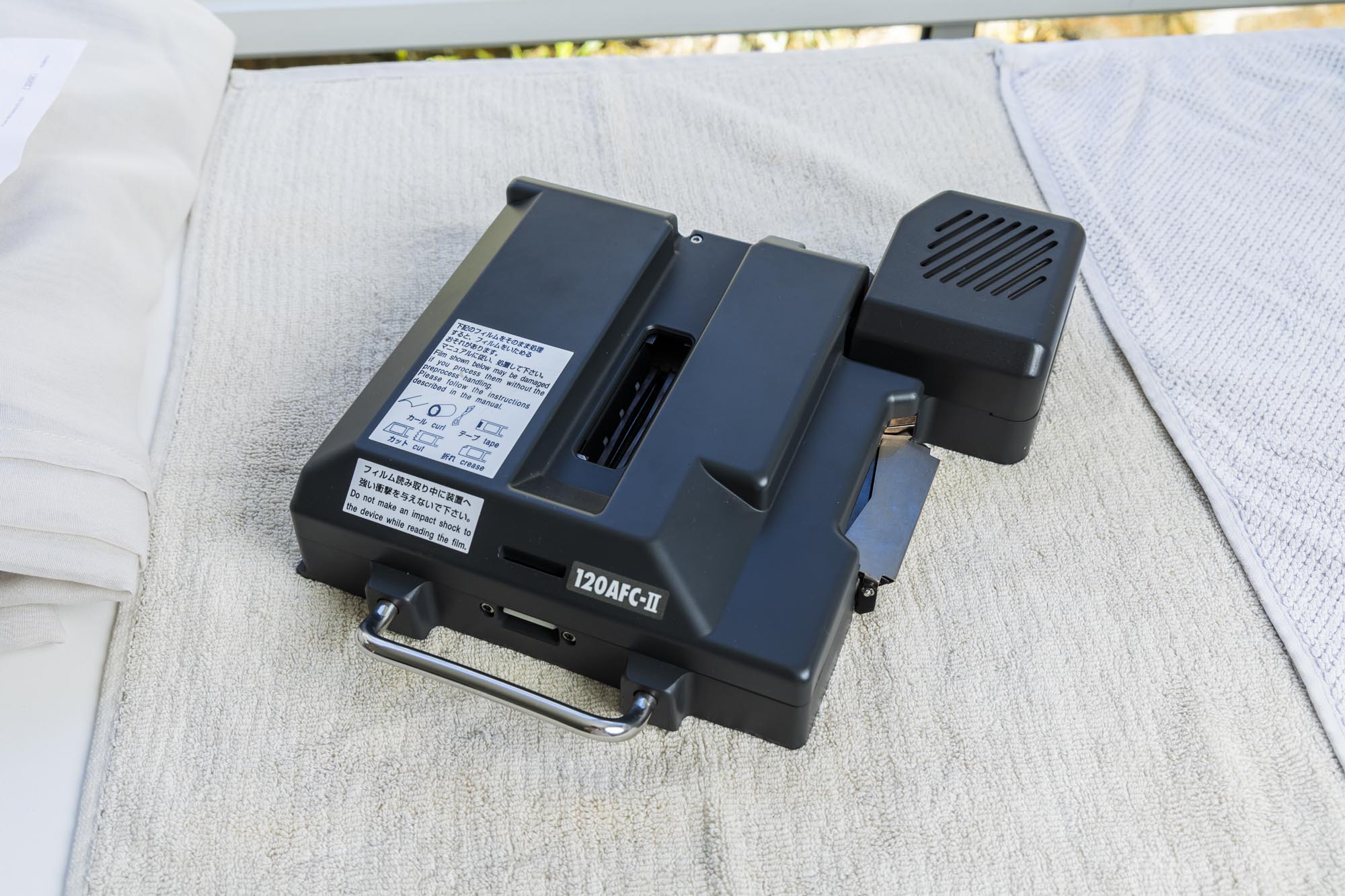
Below is the full instructions for disassembly, roller replacement, and reassembly of the Noritsu 120AFC II Carrier for S2, S3, S4, HS-1800 Noritsu Scanners.
You will need:
A Large phillips head screw driver
A T15 Hex driver or similar allen key
A T10 Hex driver or similar allen key
A tiny allen key for set screws (I'm not sure of the size, something like 1mm or 1.5mm)
A small #0 Phillips head screw driver
A good amount of space
About 2-3 Hours
Replacement rollers

Step 1
Remove the condenser lens.

Step 2
Remove 5x screws from the bottom and the 2x panels using a JIS head screw driver.

Step 3
Remove 3x small screws from inside, on the led circuit boards using a small JIS head screw driver.

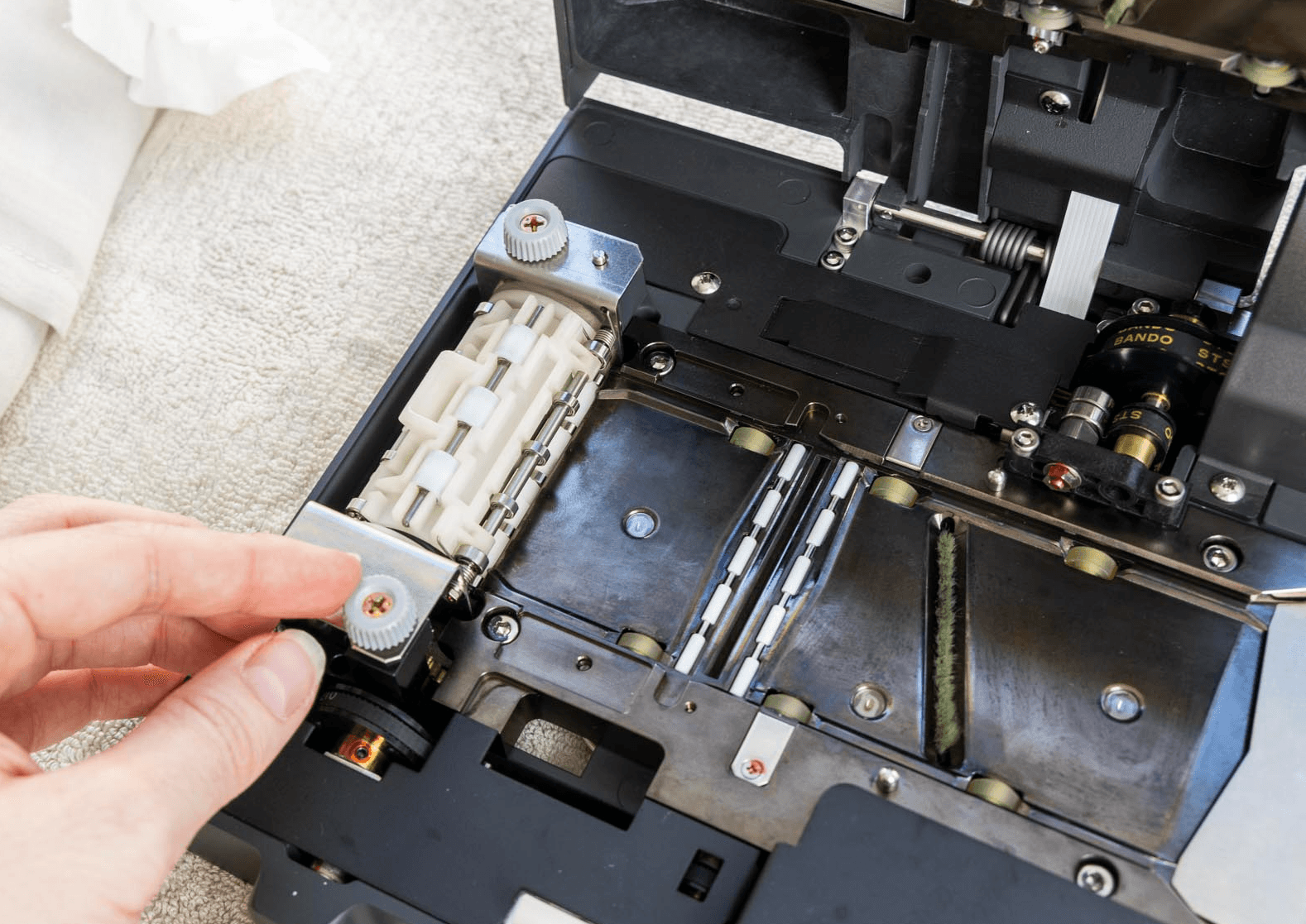
Step 4
Open the carrier, and use the thumb screws to remove the spooler part. Set aside.

Step 5
Remove 2x screws from the bottom right cover, with the bottom left screw having a washer.

Step 6
Remove 2x screws from the bottom left cover, with the bottom left screw having a washer.

Step 7
Remove the top cover with the two left most screws being like the others with no washers, the bottom right screw being shorter than the others, and the top right screw being removed with a T10 hex bit.

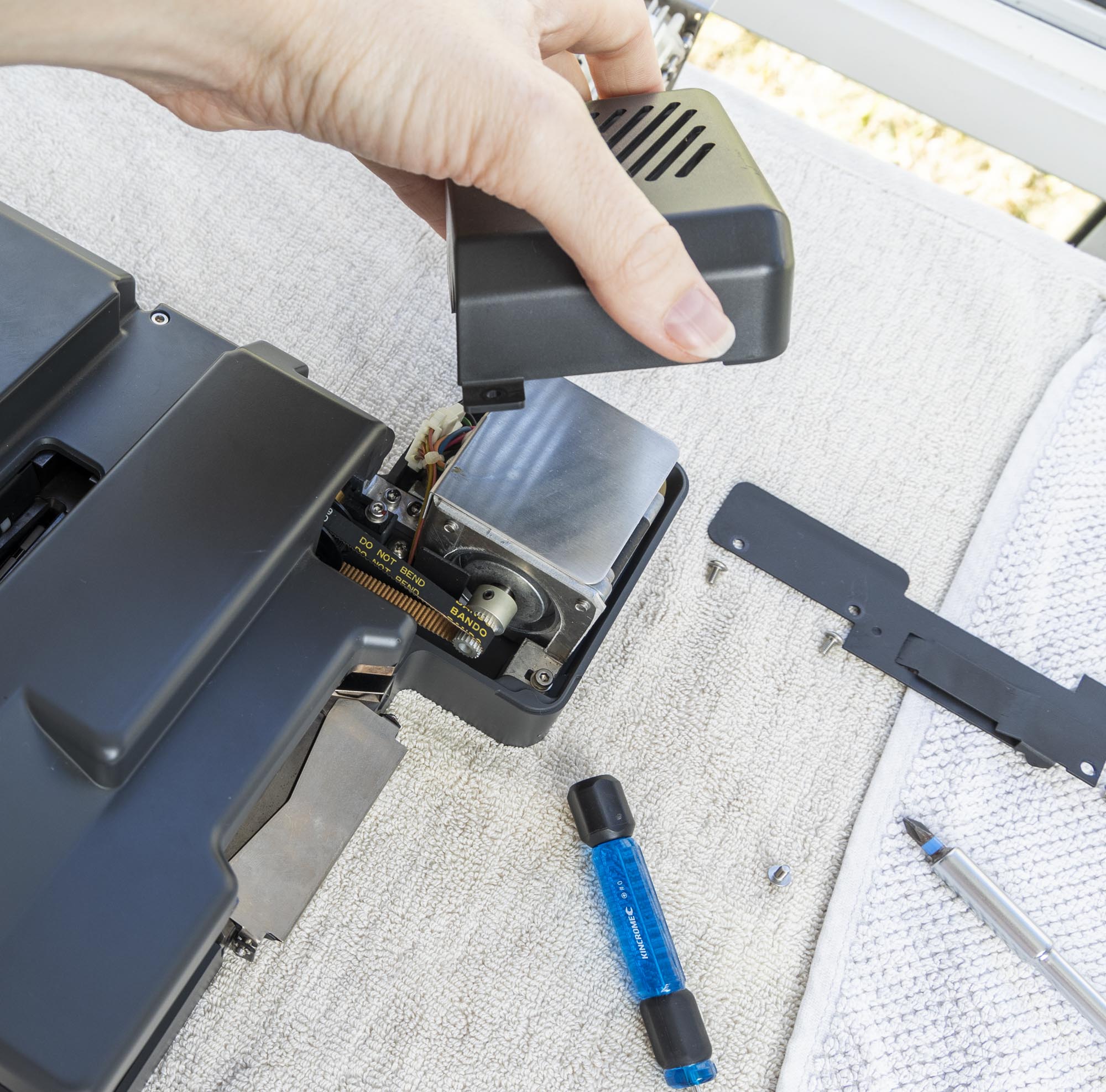
Step 8
Remove the screw holding the pulley motor cover and close the carrier, squeeze the button on the back and remove by lifting.

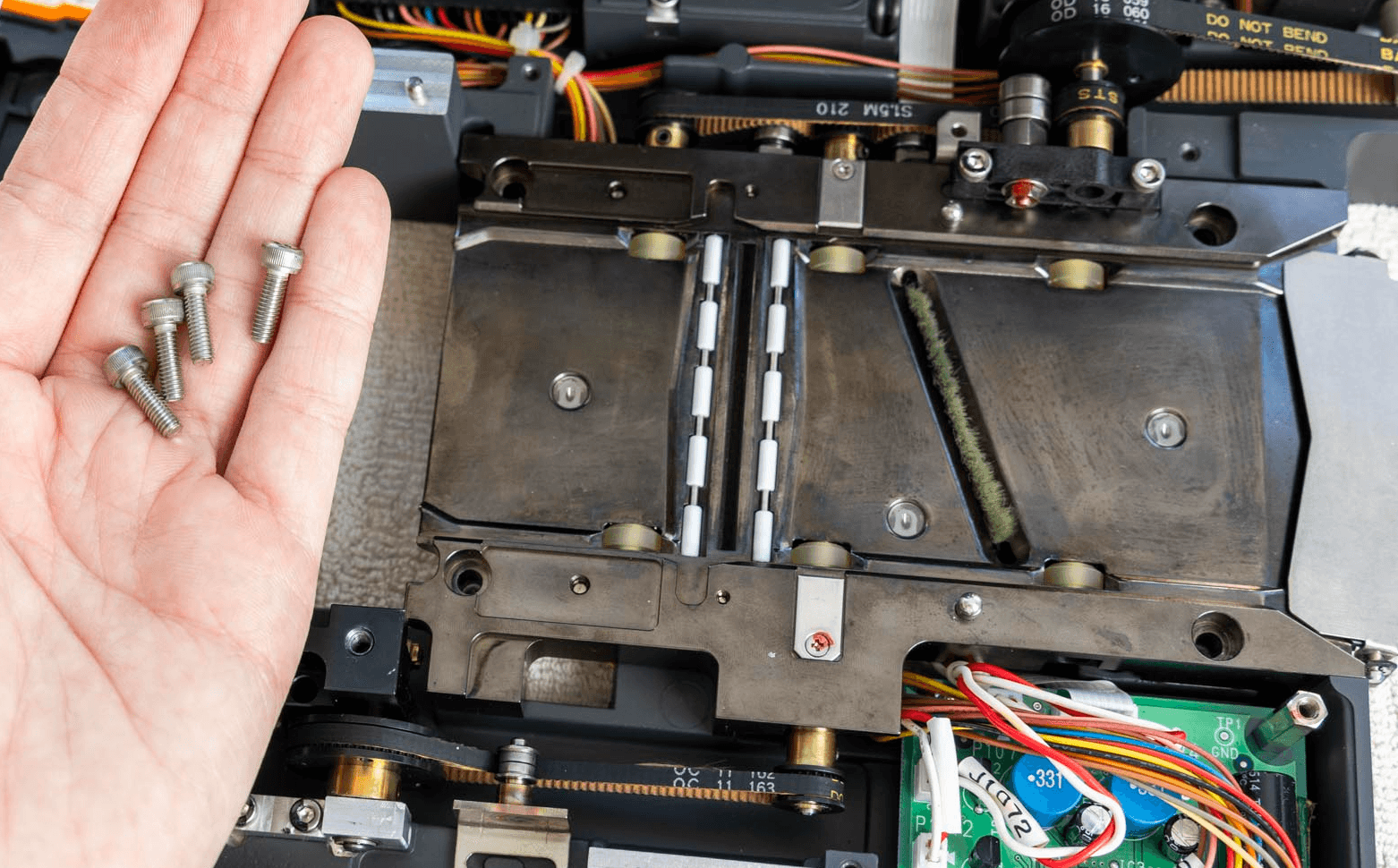
Check in
All the parts that have been removed so far.

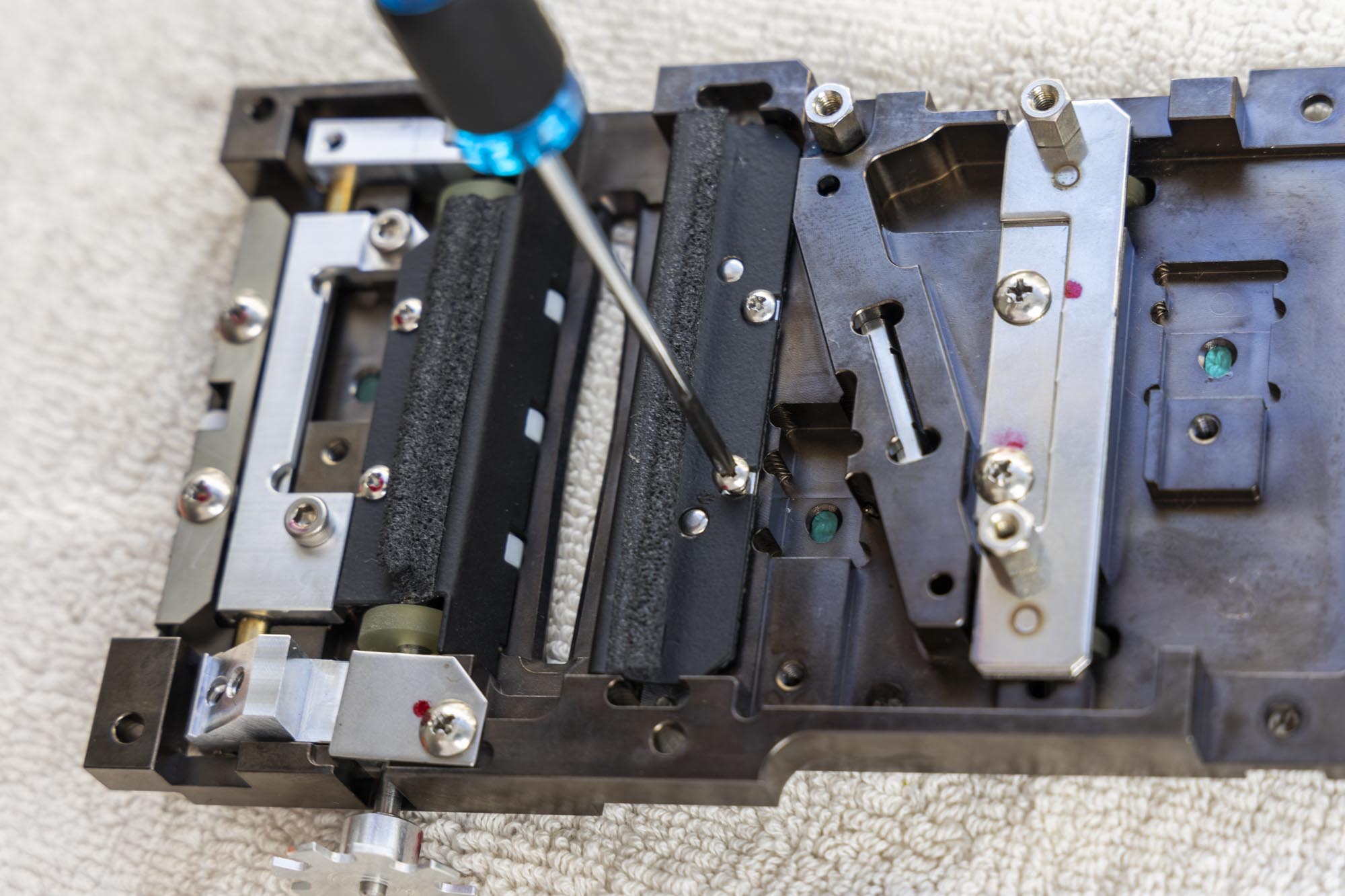
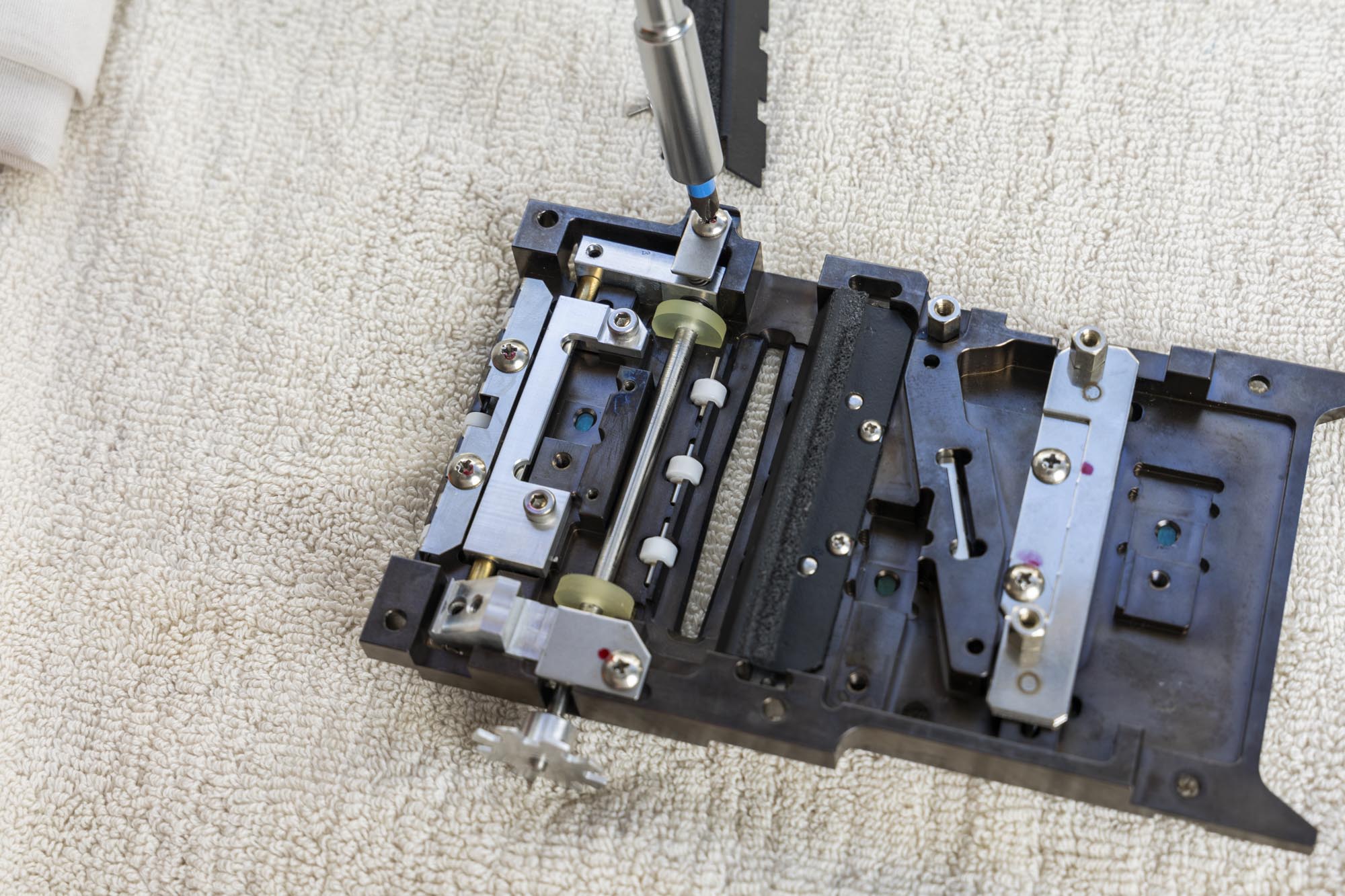
Step 9
Fully Loosen/Remove the 4x T15 bolts from the main roller panel.


Step 10
Using a T10 bit, remove the bottom belt tensioner. You can then take the belt off of the small cog.
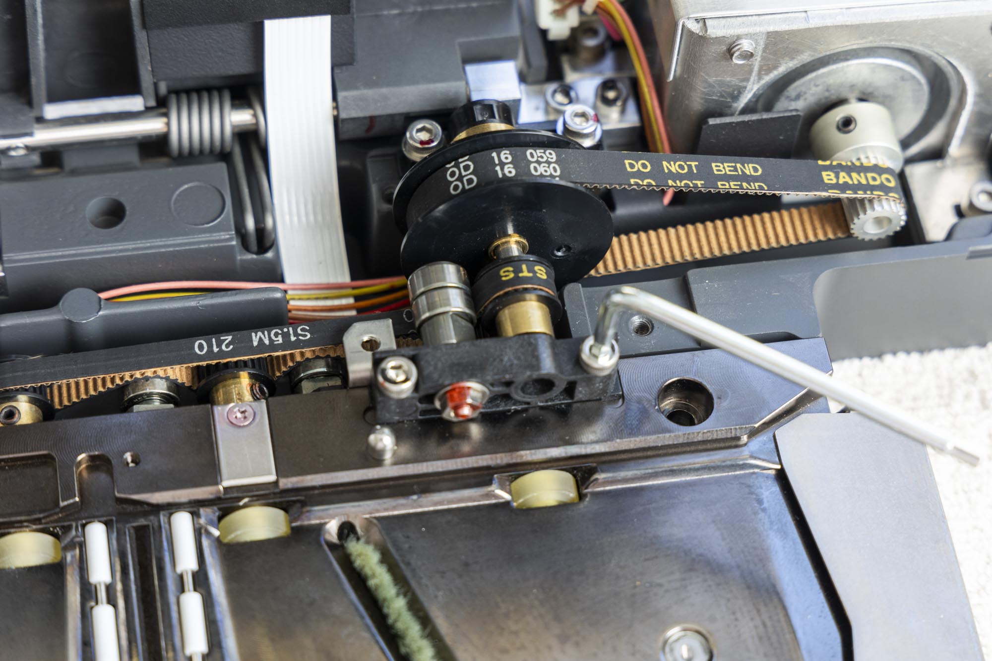
Step 11
Using a T10 bit remove the bottom 2x screws for the top tensioner.
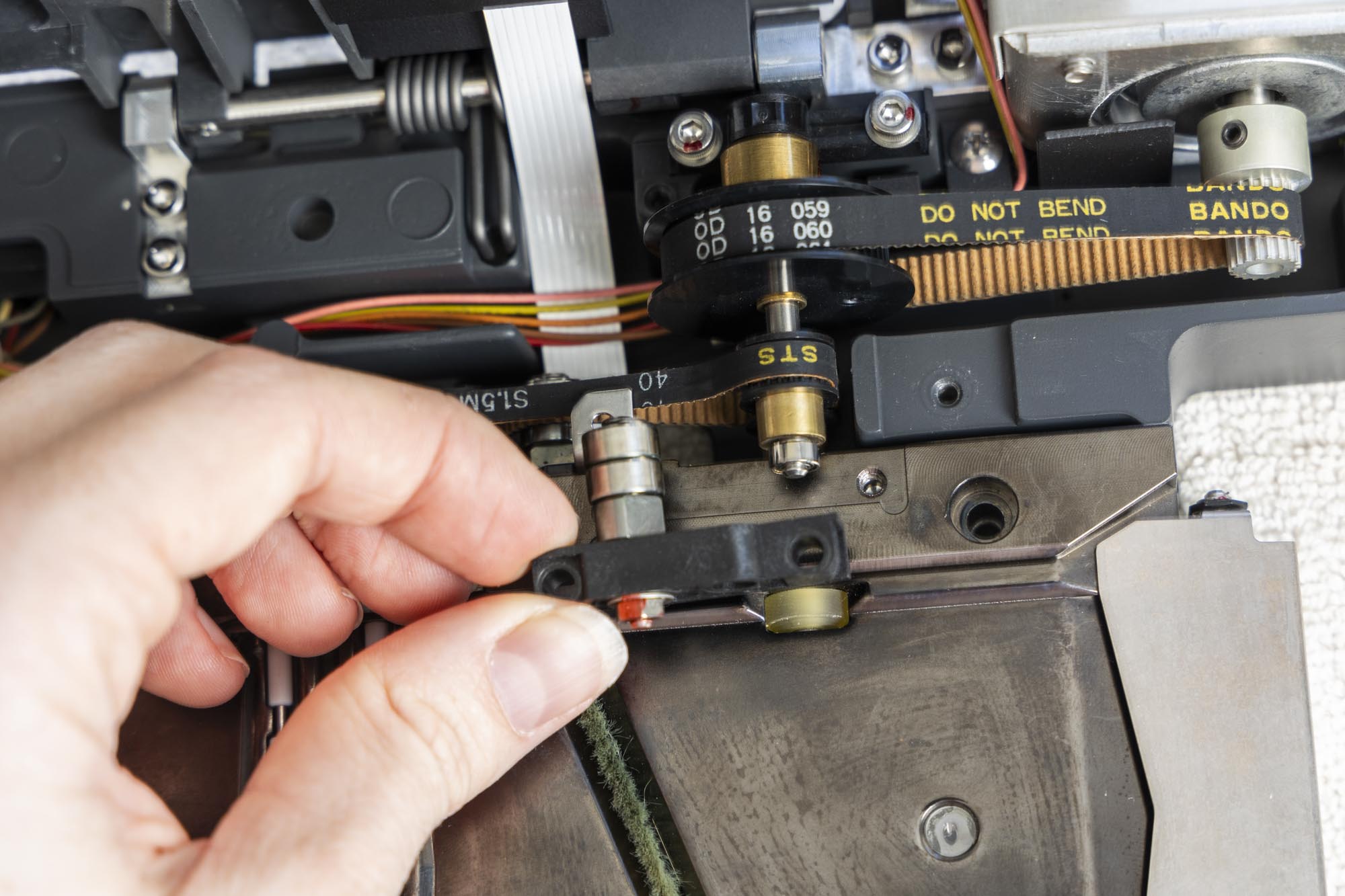
Step 12
Gently lift up and pull the tensioner away from the belt system.


Step 13
Gently pull out the main reduction gear in the same direction, careful not to lose the bearings on either side. Set it aside.


Step 14
Gently lift the roller panel. the last part is a clip holding cables, release it by pushing the outside edge towards the inside.


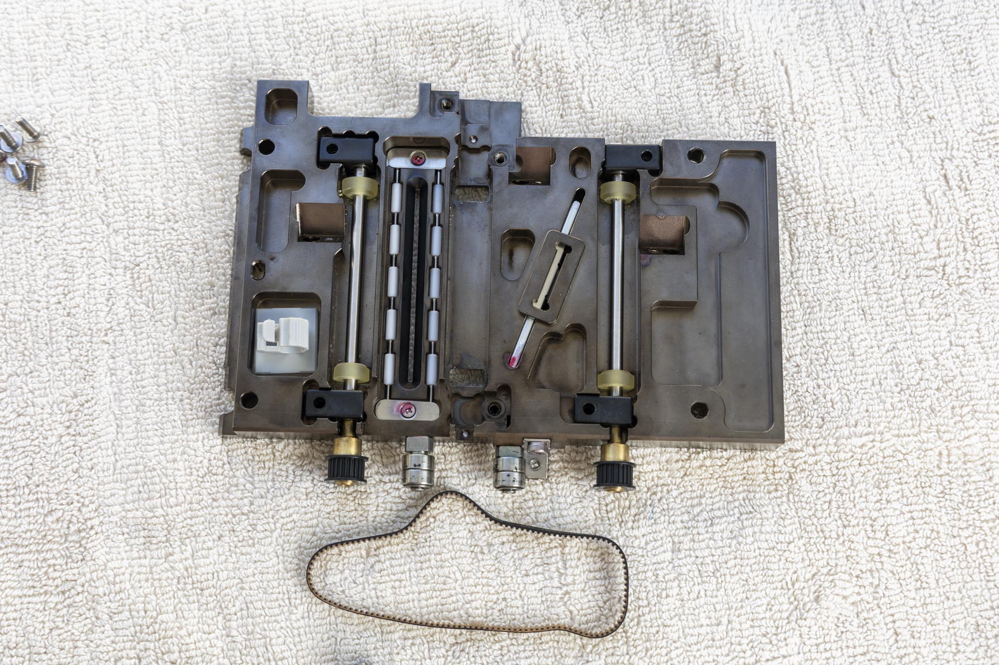
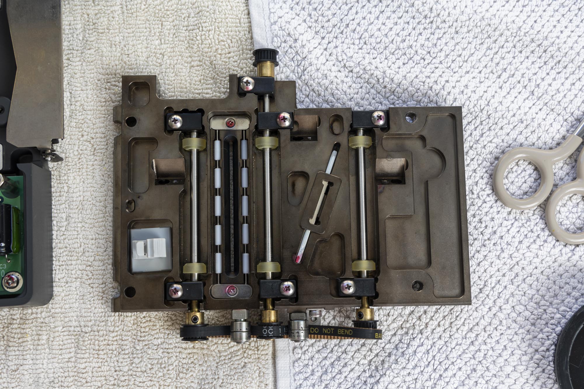
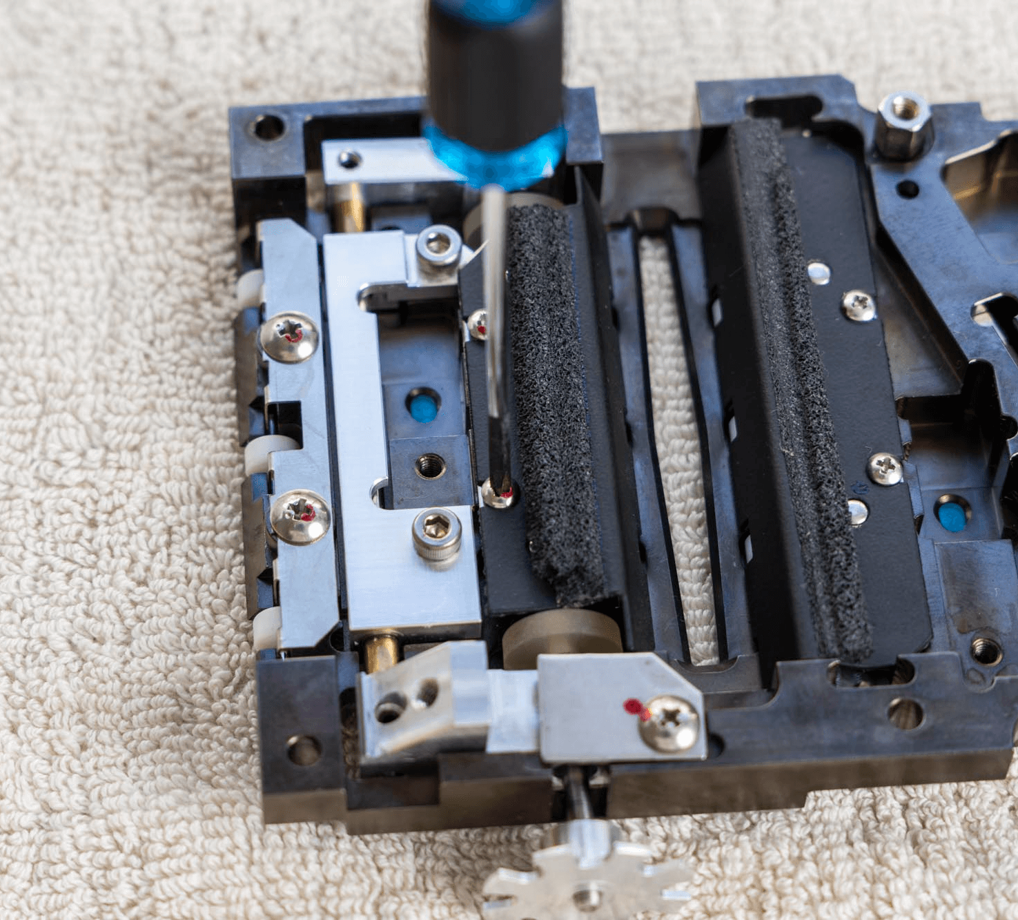
Check in
The roller panel is now free.


Step 15
Remove 6x JIS screws, the rollers will easily come out, be careful to remember the orientation of the black holders that the screws were in and to not lose their bearings.


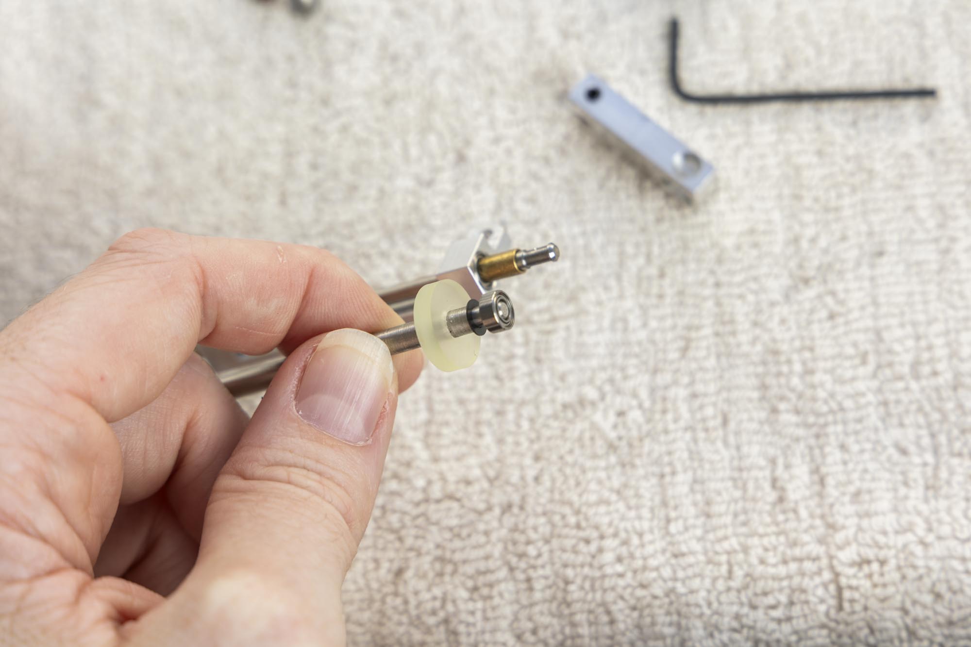
Step 16
Simply slide one of the black parts off and the rubber wheels will be able to side off by twisting the axel back and forth and holding the wheel.

Step 17
Replace the rollers with the right size replacement (no bearing, friction fit type) with the small indent side facing the inside
Do any cleaning in the panel necessary


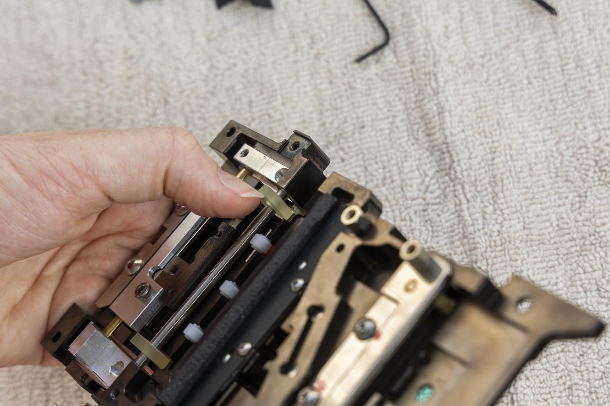
Step 18
For the middle roller, you will need to loosen (not necessarily remove) the small black set screw on the brass part to remove the cog, after this the black part can be removed and you will be able to remove the rubber rollers. Be sure to take note of the small bearings inside and their position. If it is not coming off, soak the very end of the axel with the cog in acetone or isopropyl for a few minutes (do not over soak) to loosen any gunk
Step 19
Repeat the steps for the last roller as the first.
Step 20
Reposition the rollers in their spots and check rubber rollers aren’t rubbing up to the side of anything and screw them back in. If they are rubbing, use the cog at the end to rotate the axel and push on the roller as it turns. Do not over tighten the screws for easy replacement in the future.

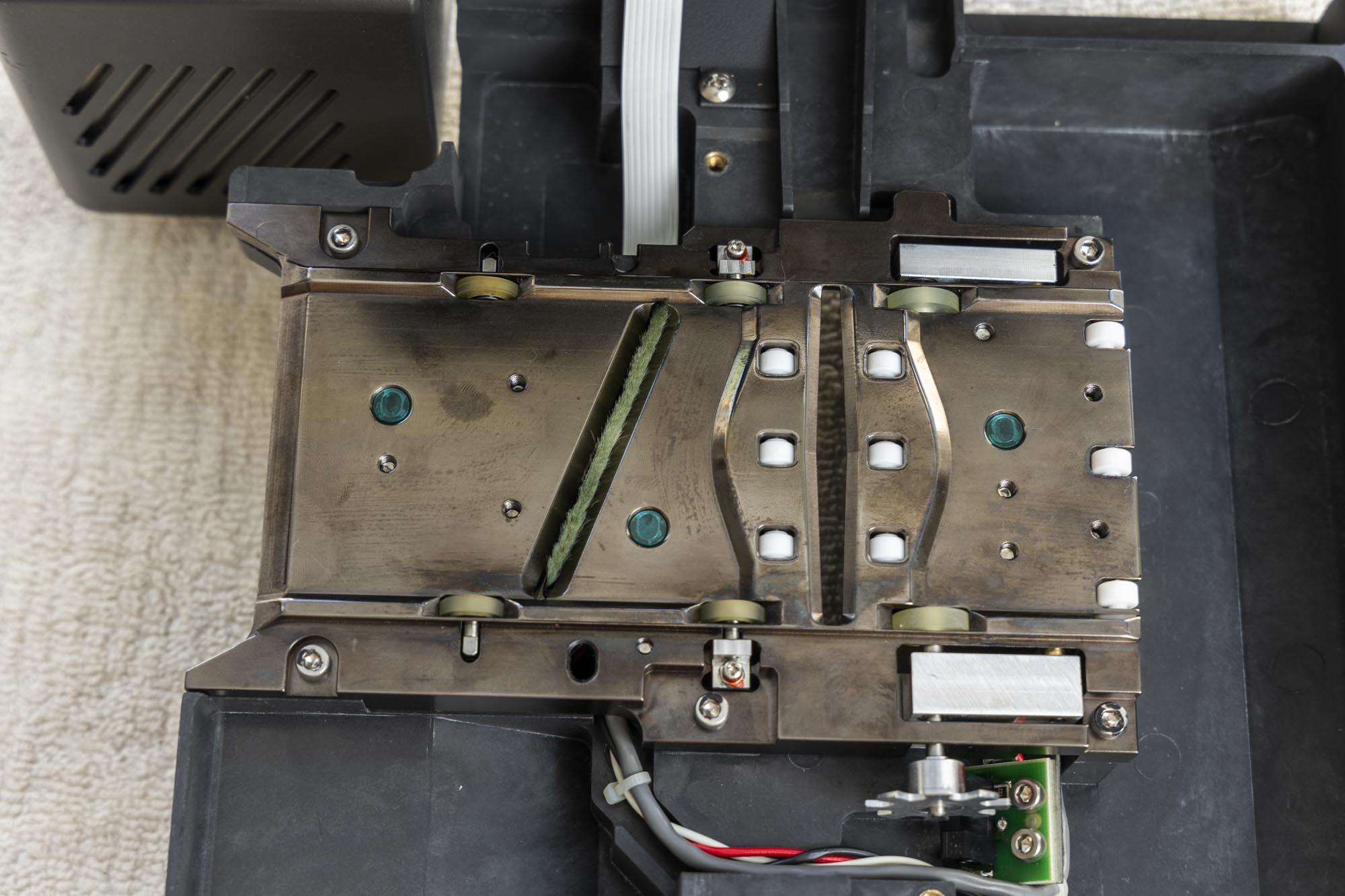
Step 21
If the belt fell off or was removed, replace as per the picture. Under the stainless bearings and over the black cogs.


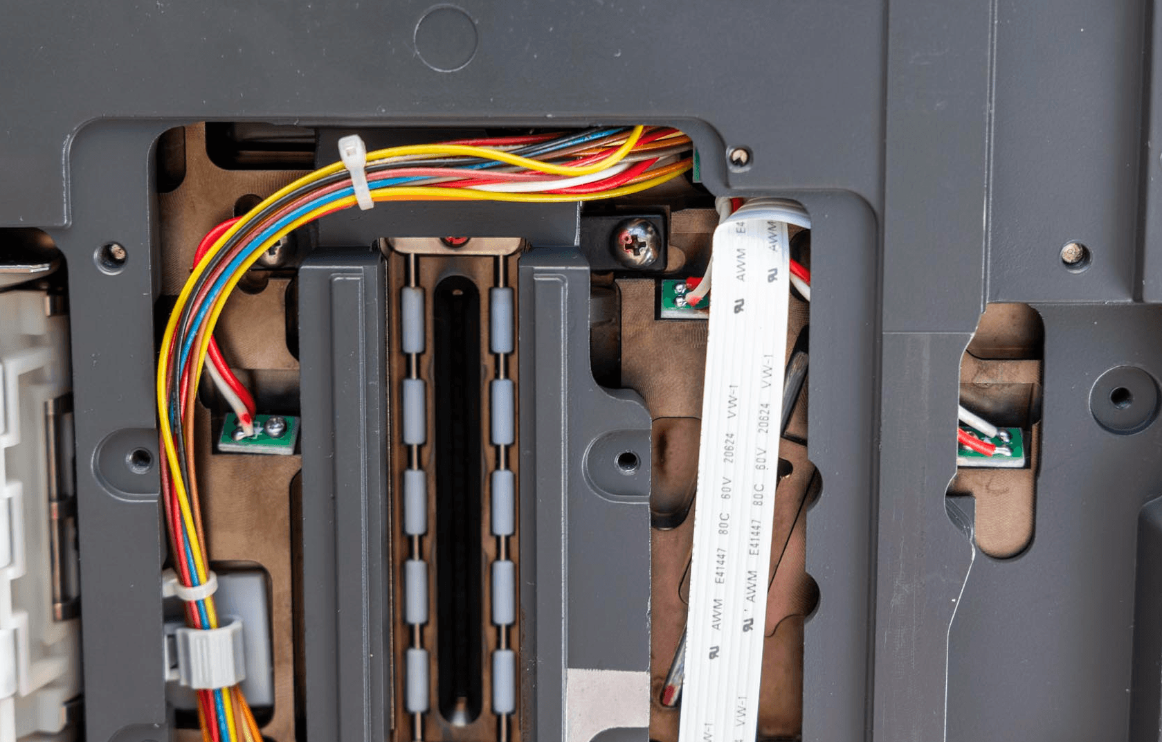
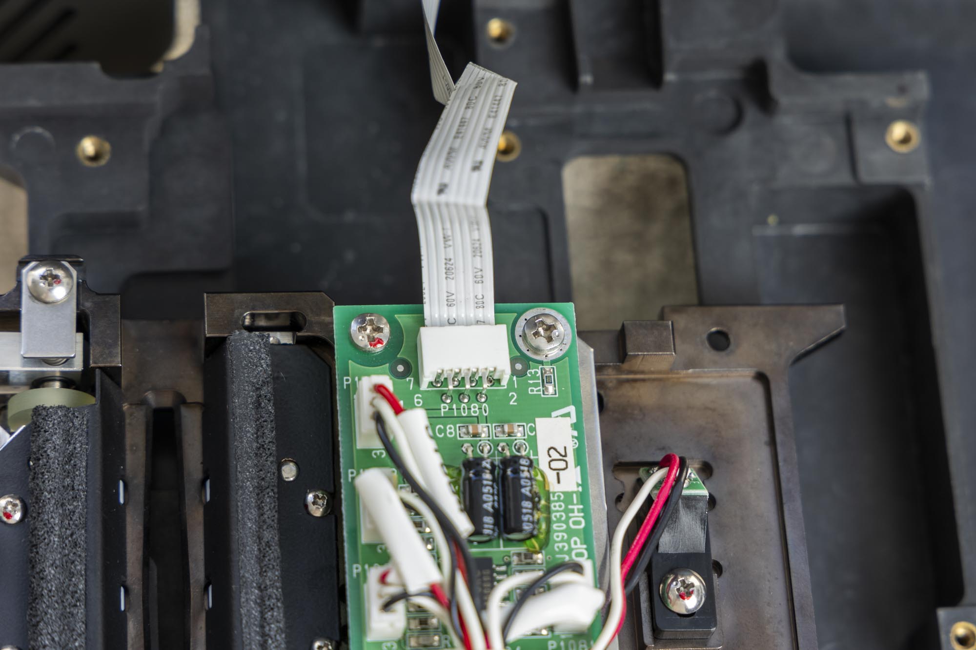
Step 22
Now replace the roller panel back in left side first, gently place it and then lift up to check the small led boards are in the generally right spot. Make sure the cables coming from the bottom right board are to the left rather than on top, otherwise the roller panel will not seat properly. Do not force anything.

Step 23
Screw the roller panel back in with the 4 T15 bolts.


Step 24
Once the roller panel is back in position, you can add back the large reduction gear. making sure it has both belts on it. Remember to make sure the bearings are on either side.

Step 25
Replace the belt tensioner for the top belt. You may need to put some pressure to get it into place. Screw back in the screws.


Step 26
Replace the 3x metal covers and remembering where each specific screw goes. The order in which you do them doesn’t matter.

Step 27
Replace the pulley motor cover, remembering this is easier closing the carrier.
Step 28
Replace the spooling part with the thumb screw.

Step 29
Turn over the carrier to the bottom, and check the location of the LEDs, if they aren’t in the correct place, give the cables a gentle tug from next to the main bard at the top right to lengthen the amount you have, then position them back to their initial spots.

Step 30
Screw them back in gently as these screws strip easily.

Step 31
Replace the panels and screw the screws in. Do not replace the condenser lens, that will be the very last step.

Check in
With this you have completed the bottom roller portion!

Step 32
Open and flip the carrier on its top so that you can work on the top side.

Step 33
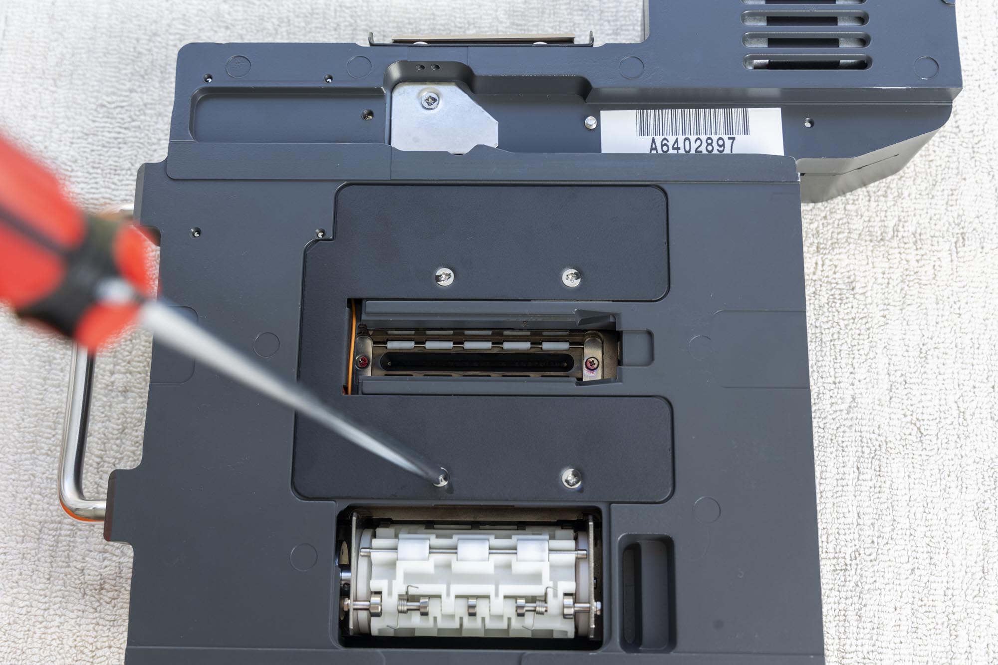
Remove the bottom plastic cover with a phillips screwdriver.

Step 34
Remove the top metal cover with a philips screw driver, the panel that appears underneath can stay in place.
Step 35
Using a T10 bit/allen key remove the 5x bolts holding the roller panel in place, There are 2 shorter ones which go on the opening side and three longer ones which go towards the right/spooling side, and middle. Set them aside.
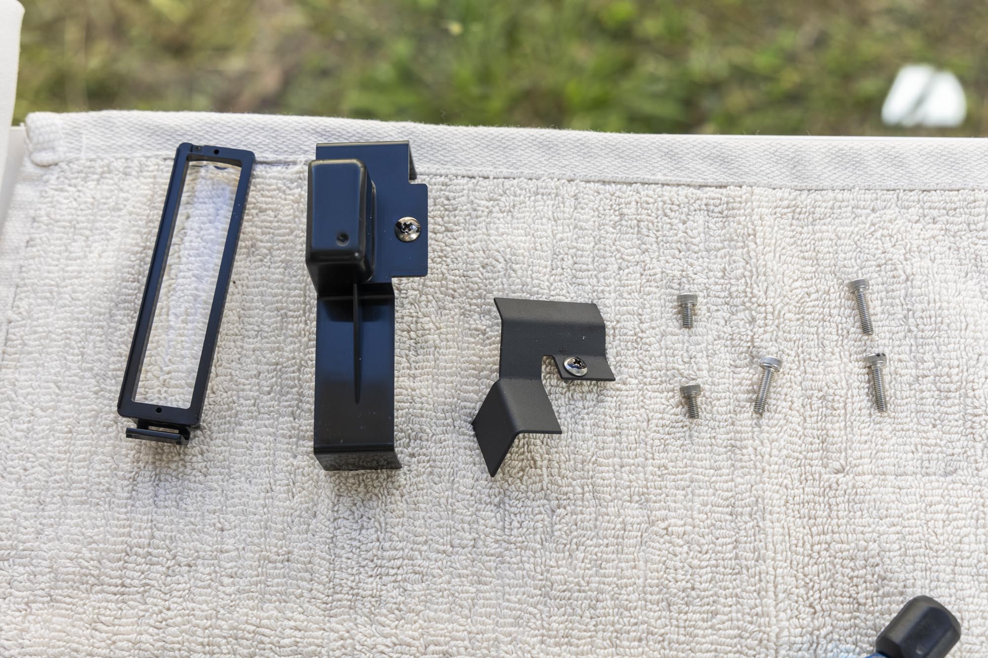
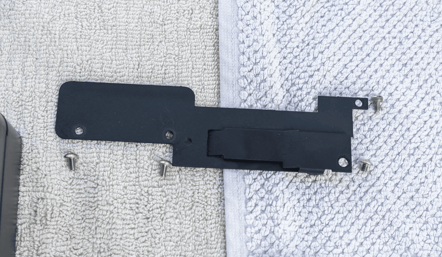
Check in
These are the pieces removed so far.


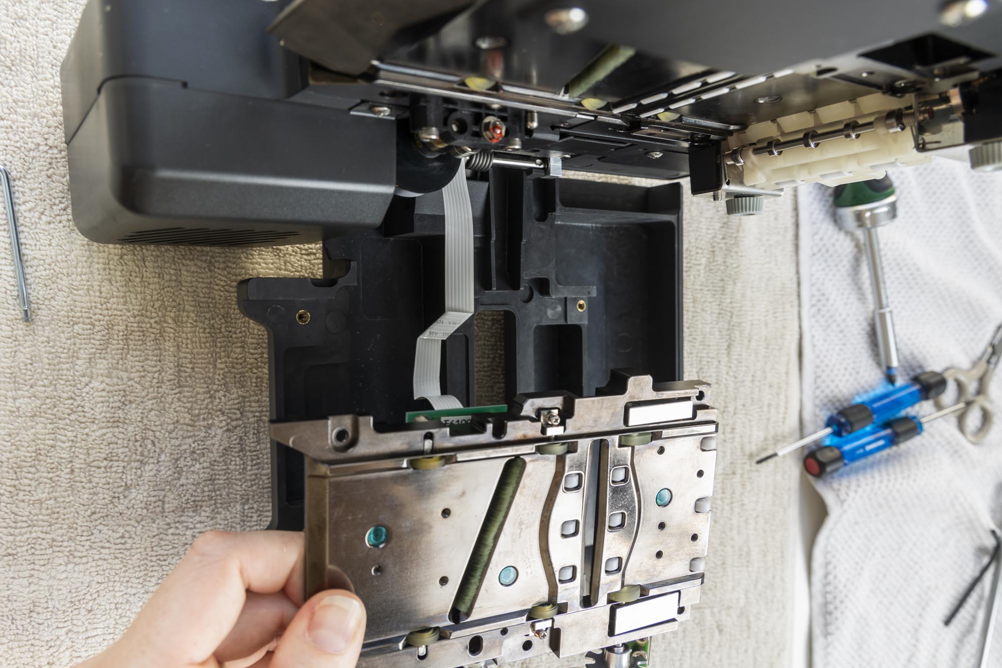
Step 36
VERY GENTLY lift the roller panel and turn over to reveal one ribbon cable that attaches it to the rest of the carrier.
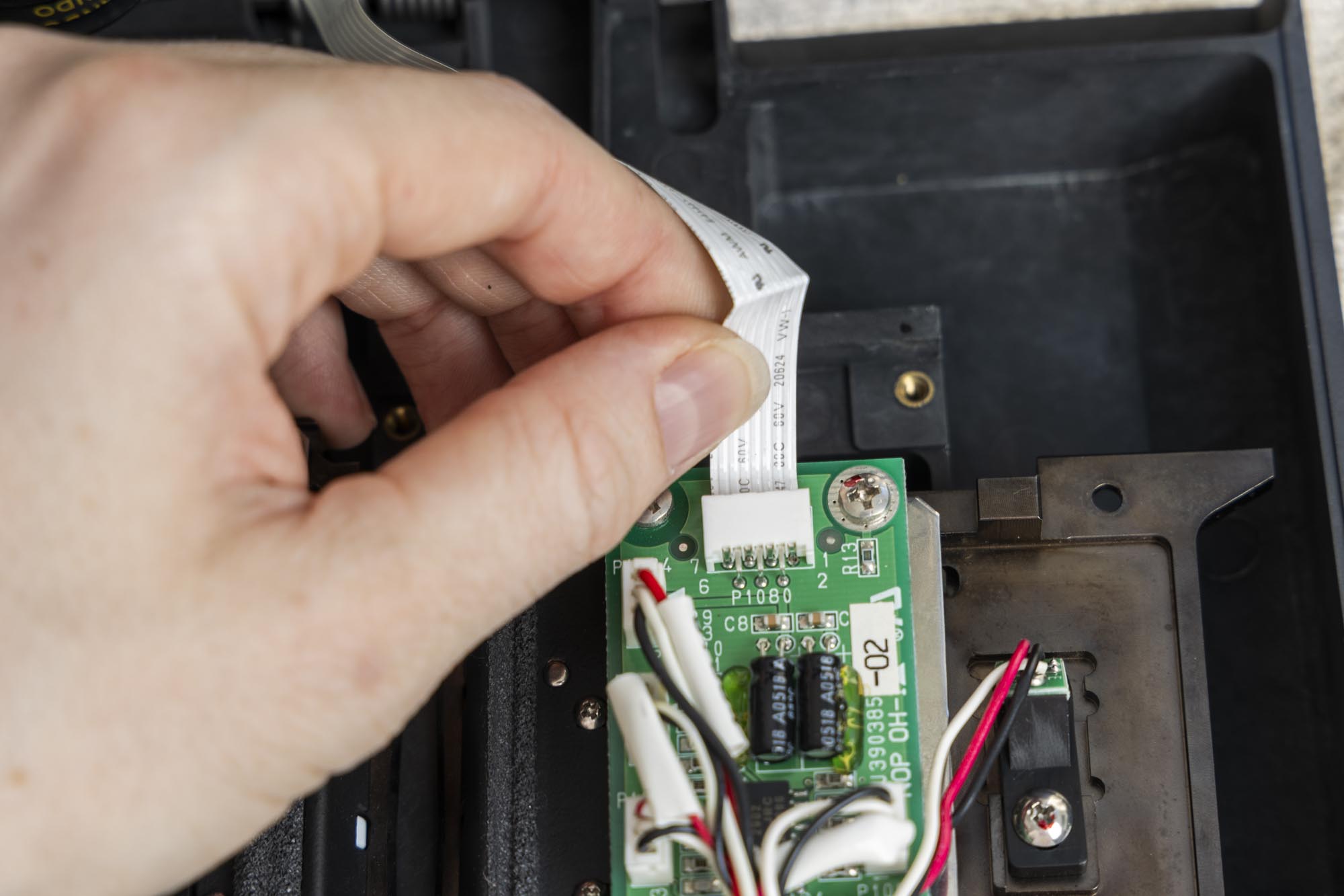

Step 37
Gently pull and rock the ribbon cable side to side to remove it. The text side of the ribbon cable faces away from the board at the connector.

Step 38
Now set aside the rest of the carrier and sit the roller panel in front of you. With the board facing up, this is the side you will do all the work on.

Step 39
There are three small boards, unscrew the first one to the right, which has a longer screw.
Step 40
The bottom left one has a shorter screw
Step 41
The Top left one has a screw like the first.

Step 42
New remove the 3 screws holding the large circuit board, the three screws are the same type.

Step 43
Next is the last T10 type bit holding the circuitry to to the roller panel. Remove this.

Step 44
Set aside the boards with the screws next to each part to easily remember.

Check in
This is what the roller panel will look like at this stage.

Step 45
Next remove the two screws holding down the panel above the right most rollers.

Step 46
Underneath is springs so make sure to remove it gently.

Step 47
With this you can remove the axel and the rollers.

Step 48
Take off the rollers but be careful with the small washers on either side of the rubber roller's bearings.

Step 49
Replace the wheels, remembering to replace the washers on either side and that the small notch out of the wheel goes towards the inside
Step 50
When putting the axel back in the roller panel, make very sure the washers are not being crushed or misaligned as they break very easily. Just place it on the slot, and let gravity pull it in, if a washer is stopping it from falling into place use a small tool to push it over to the wheel. Make sure the notches in the axel are facing up by simply pressing on them with something like an Allen key.


Step 51
Replace the springs and the plate and screw in both screws. Make sure springs are straight.

Step 52
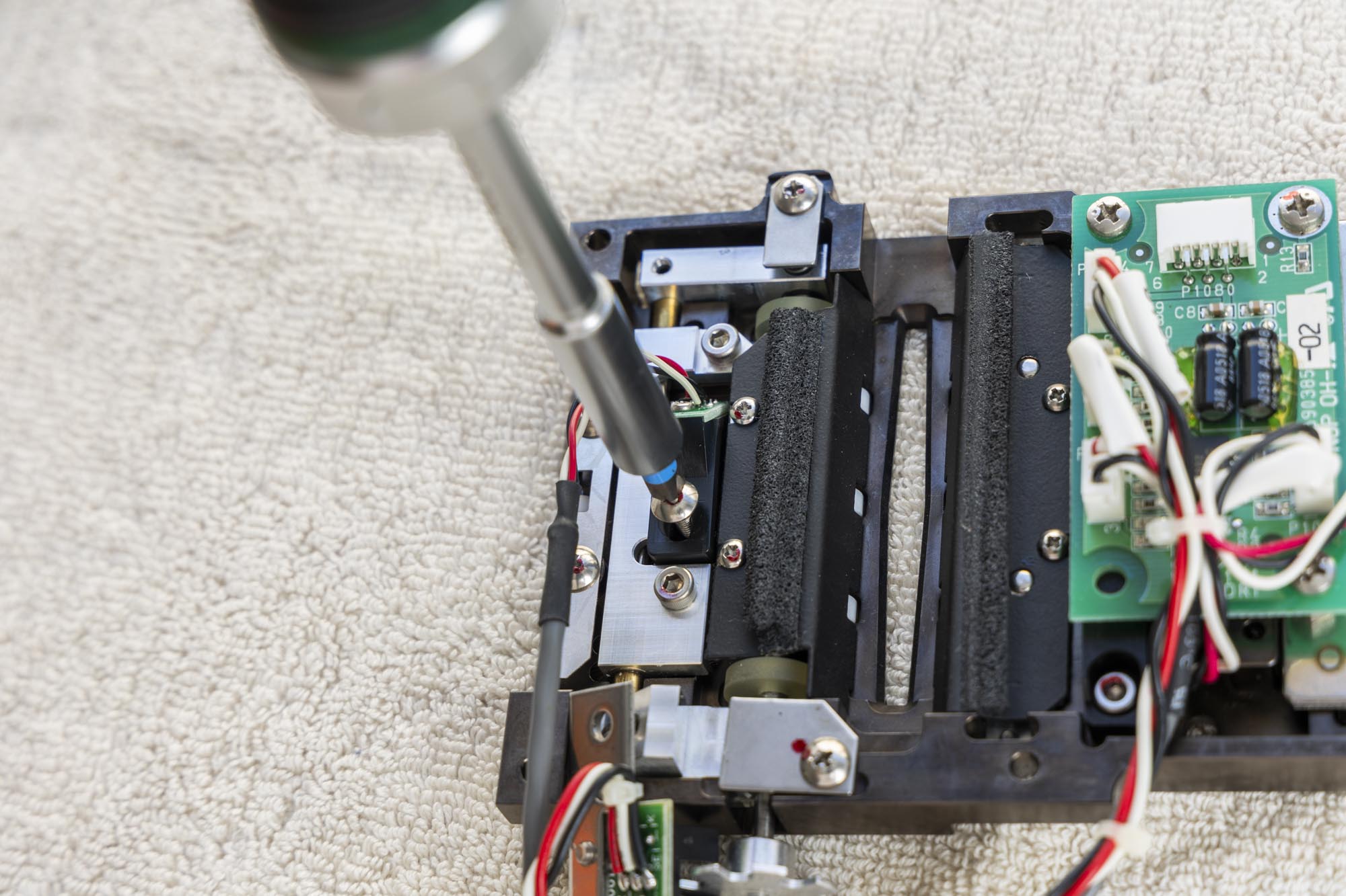
Next is the middle roller. On the black plate, remove the two small screws being careful not to strip them.


Step 53
Be careful when removing the black plate and the silver panel under that as there are more springs, set them aside.


Step 54
Remove the roller and loosen the small black set screw on the metal box at the end and remove it. You will then be able to take off the rubber wheels and replace them.
When replacing the rollers, remember that there are more washers to be very careful of. Make sure you take them off carefully (they may be stuck to the side of the old wheels), and replace them carefully on each side of the new wheels.

Step 55
When replacing the box with the set screw make sure they are aligned with each other.

Step 56
Place the rollers very gently on where it sat originally and use a small tool to gently push the washers against the wheels and it should fall down into place with gravity.

Step 57
Replace the springs and the panels which sat on top.
Step 58
Screw them in with the 2x small screws, being careful not to over tighten or strip them.
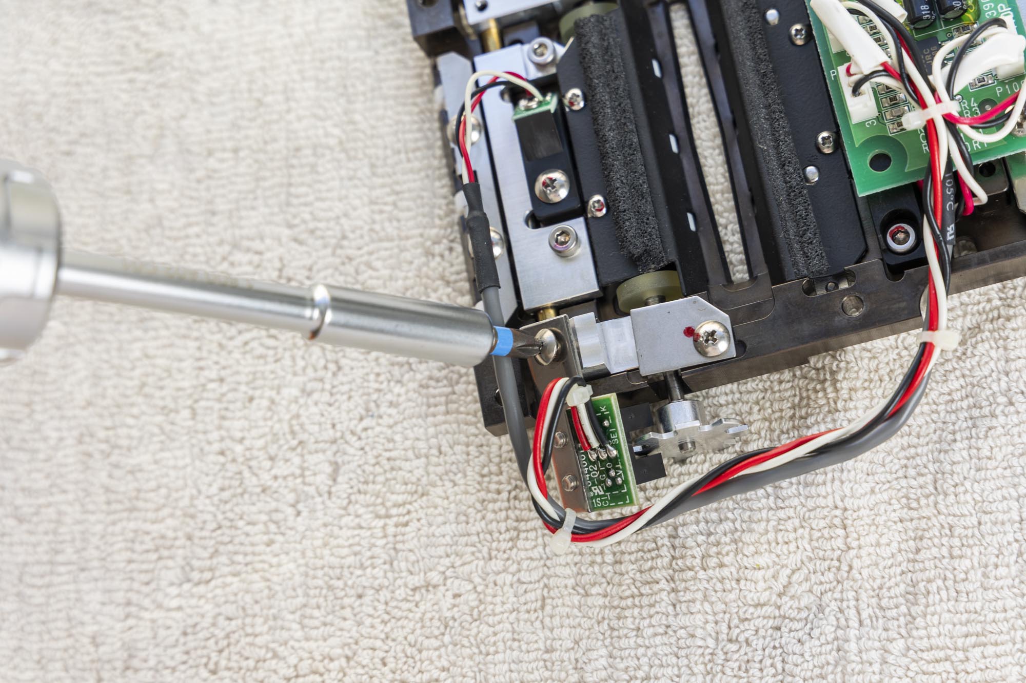
Step 59
Now unscrew the 2x small screws holding the panels on the left most axel.

Step 60
Remove the two screws holding the plates at the top and bottom of the axel, these have springs underneath so remove them gently

Step 61
Unscrew the T10 bolds holding the remaining pieces on. This will allow you to remove the axel assembly.

Check in
All the pieces removed for the left axel.


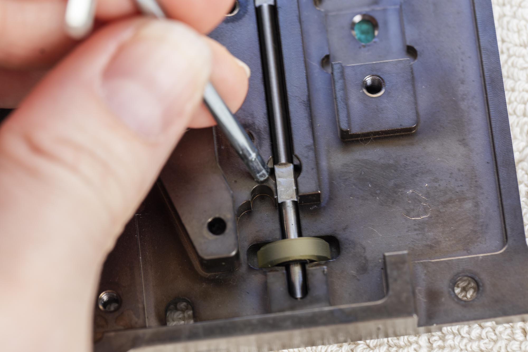
Step 62
Simply loosen the set screw on the end block and the block should come off of both axels. You can then remove the bearing if it came out of the block and be careful again of the washers.

Step 63
Replace the two wheels, they are friction fit and there is a rough spot on the axel where it sits.

Step 64
Replace the block and tighten the set screw, applying gentle pressure to both sides.

Step 65
Put the assembly back in and screw in the two T10 bolts.
Step 66
You can then straighten and align the wheels by putting a gentle pressure on one side and rotating the axel.

Step 67
Replace the springs.
Screw on the plates above the springs, ensuring they are straight.
Step 68
You can then straighten and align the wheels by putting a gentle pressure on one side and rotating the axel.

Check in
Next is the circuitry.

Step 69
Start with screwing in the small T10 bolt

Step 70
Next screw in the 3x phillips head screws in the large board.

Step 71
After that the small photo receptor board to the right, try to position it so that it is as close to you as possible when in the same orientation as the photos.

Step 72
Next the small bottom left board, its the one with the slightly shorter screw. Ensure that the axel cog looking thing is not touching the board.

Step 73
Next the top left board. Again ensure it is slid close to you when the roller plate is in the same orientation as the photos.

Check in
With that the plate is complete and it’s time to reassemble it onto the carrier.

Step 74
Place the plate on the top lid of the carrier, and hold the ribbon cable so that it is not too twisted but with the writing facing away from the board, see photos. (One side of the ribbon cable is white and one has writing, you should be able to see the writing in this orientation.
Step 75
Connect it by applying gentle pressure and rocking back and forth, it should stop going in when it is seated correctly, don’t put in too much pressure as they are fragile.
Step 76
Now rotate the roller plate either clockwise or counter clockwise so that the ribbon cable becomes flat (with some turns in it) see photo.

Step 77
It should then seat nicely into place.


Step 78
You can now screw back in the T10 bolts that hold the plate in place. Remember the left two near the opening have the two short ones and the right two and middle are longer.
Check in
It should be nicely back into place. Next up is the covers

Step 79
First the back cover for the ribbon cable, just one screw.

Step 80
Next the front cover for the sprocket thingo, just one screw as well.

Step 81
With that it's finished!
Step 82
Give everything a dust a replace the condenser lens.

Finish!
Make sure to refocus and do some tests before first using the carrier.